Hardware Connection
You need a soldering iron and 4 jumper cables. Then, solder 4 wires to the pins: GND, DC, DD and RST of the CC2531 header (see CC2531 Pin Header in Fig. 1a). The header is very small and you can bend the pins a little, if you cannot solder them directly.
However, if you are not good at soldering, or if you don't have any soldering iron, you can buy the following adapter:
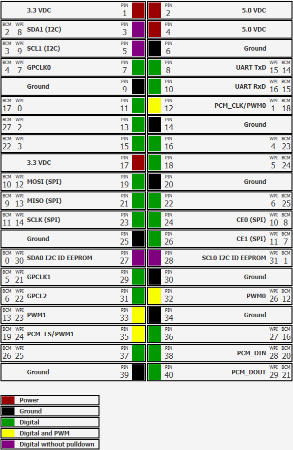
The adapter connects using a flat cable to the CC2531 and it has a bigger pin header on board side. Thus, you can connect the female jumper connectors directly to that header (see CC Debugger Pin Header in Fig. 1a). It doesn't matter which option you have chosen (solder or adapter), but then, connect the other end of the wires to the Raspberry Pi header (see Fig. 1b) as described in the following table:
| Raspberry Pi | CC2531 |
| GND | GND |
| Pin 38 | DD |
| Pin 36 | DC |
| Pin 35 | RST |
After connecting the CC2531 header to the Raspberry Pi headers, plug the USB dongle to a USB port of the Raspberry Pi and then, power up the Raspberry Pi.
 |
 |
| Pinout CC2531 | Pinout Raspberry Pi |
Flashing the CC2531
- On the Raspberry Pi, check if you have already installed Wiring Pi typing:
gpio -vin the terminal. If not, install it following these instructions. - Clone the jmichault/flash_cc2531 repository typing the following:
git clone https://github.com/jmichault/flash_cc2531.git - Go inside the
flash_cc2531folder and check if the Zigbee-USB dongle is wired correctly and if it's identified:cd flash_cc2531 ./cc_chipid - You should see
ID=b524. If you get any other text (e.g.0000orffff), re-check your wiring. - Download the latest firmware from Koenkk/Z-Stack-firmware.
wget https://github.com/Koenkk/Z-Stack-firmware/archive/master.zip unzip Z-Stack-firmware-master.zip # (**) cd Z-Stack-firmware-master/coordinator/Z-Stack_Home_1.2/bin/default/ # (*) unzip CC2531_DEFAULT_<<yyyymmdd>>.zip - Erase the CC2531 flash with
./cc_erase - Flash the firmware using
./cc_write /path/to/CC2531ZNP-Prod.hex. This will take about 3 min. - Disconnect the wires/adapter and reboot the Raspberry Pi
yyyymmdd with the actual date of the file (check it here: /bin/default, /bin/source_routing). (**) Note 2: I used the default version of the Z-Stack coordinator. But:
- a. If you have a network of 1 - 30 devices, the Z-Stack_Home_1.2 /bin/default firmware is recommended.
- b. If you have a network of 30+ devices, the Z-Stack_Home_1.2 /bin/source_routing firmware is recommended.
Use other pins:
all commands accept the following arguments:
-
-c pin: change the DC pin (default 27)
-
-d pin: change the DD pin (default 28)
-
-r pin: change the reset pin (default 24)
-
-m : change the delay multiplier, and therefore the base time (default: automatic adjustment)
the pin numbering used is that of wiringPi . use gpio readallto have the arrangement in your Raspberry (column wPi ).
For example, if you want to use pins 11, 13 and 15:
Connect the following pins from debug port to GPIO port :
Colors for my downloader cable!!!
-
pin 1 ( GND ) -> pin 9 ( GND ) BROWN
-
pin 7 ( reset ) -> pin 11 ( wPi 0, BCM017) GREEN
-
pin 3 ( DC ) -> pin 13 ( wPi 2, BCM27) YELLOW
-
pin 4 ( DD ) -> pin 15 ( wPi 3, BCM22) WHITE
and now you can read ID, save, erase and write flash memory with the following commands:
./cc_chipid -r 0 -c 2 -d 3 -m 300
./cc_read -r 0 -c 2 -d 3 -m 300 save.hex
./cc_erase -r 0 -c 2 -d 3 -m 300
./cc_write -r 0 -c 2 -d 3 -m 300 CC2531ZNP-Prod.hex
Use the "-m 300" option to increase the timeouts used for RPi 1B.